Following is the blog entry I have already posted in Japanese. I try to translate this into English this time.
Today is the IoT/Smart Connected Device Practice. Let’s create an application to monitor the temperature, humidity and air pressure measured by BME280 and ESP8266.
These are today’s ingredients. I procured them from Switch Science and Akizuki Electronics. The total material cost is about 3,000 yen, all of them are available on EC sites on the Internet. It’s a good time.
BOM List
1.ESP8266 ESP-WROOM-02 Development Board (Switch Science)
2.pin header
3.BME280 Temperature, Humidity and Pressure Sensor Kit (Akizuki Electronics)
4.breadboard
5.jumper wire
6.USB cable
The process for creating a Smart Connected Device is as follows:
Through each Stage, I have decided to prioritize programmatic configuration over physical implementation as our design philosophy.
*Creation process
Stage-1 Device Production (BME280/ESP8266)
Stage-2 Device Integration on Breadboard
Stage-3 Get Smarted
Stage-4 Connect to the Internet via Wifi
Stage-5 CloudApps colaboration
*Stage-1 Device Production
I got ESP8266 and BME280, but I was at a loss as I was inexperienced. Switch Science shows lots of examples with BME 280 and ESP-WROOM02 development board.
However, there are few sites that introduce the combination with BME280 of Akizuki and ESP 8266 of Switch Science. While I was wondering if I failed, I managed to find it.
This site gives me confidence.
*Build a Temperature, Humidity and Pressure Monitoring System in 15 Minutes with the ESP-WROOM-02 Development Board – Qiita
There was a bonus. I was also shown the existence of “Blynk” platform that makes it easy to control and monitor Arduino on iOS and Android.Now, with a trowel in one hand and a solder in the other, I am making a device.
You must choose the serial communication method between BME280 and ESP8266. the candidate are SPI and I2C. The example in Switch Science seems to be SPI. However, as a lazy person, I chose I2C, which is supported by Arduino Wire Library. In this case, however, I have to make the jumper connection on the BME 280 board. I have confirmed from source that 2 pull-up resistors (J1/J2) can be configured by ESP8266 (Arduino) using a wire library.
*Verified Source
./hardware/arduino/avr/libraries/Wire/utility/twi.c
//activate internal pullups for twi.
digitalWrite (SDA, 1);
digitalWrite (SCL, 1);
I processed only jumper J3 for I2C system. It was a hard time. The processing part on the board is about 2 millimetres, so I can only know if the processing was successful with a loupe. When I checked with the loupe, the solder doesn’t come out. I had no choice but to process the jumper with a resistor tin wire at hand. Whew.
ESP8266 also needs processing. The pin header must be soldered to connect to the breadboard. I don’t know unless it’s a loupe. This is another small job. I’m not good at it, and the solder doesn’t come on easily. It turns out that if you have solder on the soldering iron, it will fail. After that, I will clean edge of it frequently and it work. Soldering requires skill. In addition, check it visually with a loupe, and check the continuity with a tester. It has 10 pins, so it is 2 x 10 checks. Whew.
*Stage-2 Device Integration on BreadBoard (BME280/ESP8266)
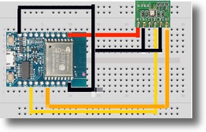
Now, let’s change places and connect the BME280 and ESP8266 on the breadboard with wires. I describe this with Fritzing. Thank you. Let’s take a look at the examples of our predecessors.
~ Library/Arduino 15/packages/esp 8266/hardware/esp 8266/2.3.0/variants/generic/pins_arduino.h
static const uint8 _ t SDA = 4;
static const uint8 _ t SCL = 5;
It turned out to be a simple passage.
ESP 280 – IO4 – > BME 8266 – > SDI
ESP 280 – IO5 – > BME 8266 – > SCK
*Stage-3: Get Smarted
From this Stage, I switch to a software engineer and build this environment by coding with Mac Terminal App screen. The source mentioned above includes the following four libraries, so you need to add them. The Wire library is the standard Arduino library and does not need to be installed separately.
# include
# include
# include
# include
First, install the ESP 8266 libraries. ESP8266 community is very strong, isn’t it.
1.Installing the ESP 8266 Libraries
*First, install Arduino IDE 1.6. 5 from the Arduino website.
*Launch Arduino and enter the following URL in the Preferences Additional Board Manager:
->”http://arduino.esp8266.com/stable/package_esp8266com_index.json”
*Open Boards Manager with Tools > Board and install esp8266 platform from menu
*Tool > Board > Generic ESP8266 module to change the Board to ESP8266
*Change the PORT setting referring to the description by SWITCH SCIENCE.
Flash Mode DIO to QIO
Flash Frequency 40 MHz
Upload Using Serial
CPU Frequency 80 MHz
Flash Size changed from 512 k (64 k SPIFS) to 4M (3M SPIFFS)
Reset Method ck to nodemcu
Upload Speed 115200
Serial Port Development Board Serial Port Number
Now you don’t have to keep pressing the IO0 mode switch button every time you upload.
3.Install BME 280 Libraries
Download the BME280 library zip from Github and install it in ~Documents/Arduino/librariy
4.Install Blynk Libraries
*Download Blynk_v0.3.1.zip
*Unzip
*Stop Arduino IDE
*Move the following in the Unzipped folder to ~Documents/Arduino/libraries
BlynkESP8266_HardSer
BlynkESP8266_SoftSer
Blynk
SimpleTimer
*Launch the Arduino IDE
5.Confirm
Now, how does this sound? OOPS! Arduino IDE validation fails. I ran the sources in ESP 8266 and Blynk’s Example little by little to see the environment. Now that ESP 8266 appears to have no problems, we’ve changed our strategy to write our own source using Example.
The reference source is here.
Example > Blynk > BoardandShields > ESP 8266 _ Standalone
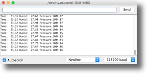
I was able to check the temperature, humidity, and air pressure on the Serial Monitor by pasting the code of my predecessor little by little while checking the operation of Example>Blynk>BoardandShields>this source. Phew.
*Stage-4 Connect to the Internet via Wifi
If you set the source to SSID, PassWord, and load it into ESP8266, the ESP8266 will simply initiate a WiFi connection.
*Stage-5 CloudApps Colaborationr
A cloud service called Blynk is open to the public on a community basis.

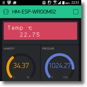
With Blynk, ESP8266 sends data generated by sensors (BME280) over WiFi to Blynk, which can then be viewed from the Blynk app installed on Arduino. I tried to make this kind of application on the cloud side by myself, but it already existed. This level is sufficient for personal use.

In parallel with downloading the Blynk app to Android, ESP8266 connects to the Blynk server with the blynk library and then configures the Blynk widget on Android.
Hi, Voila!
I stumbled in the initialization process of the send buffer and could not display the decimal point, but I finally had realized how bad it was and I was able to display it to the decimal point. Blynk, a little more documentation would be great.
And refine the design? only.
That’s it.
This productivity is perfect!
コメントを残す